|
|||||||||||||||
|
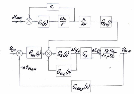
Based on the transfer functions of the generator (Section 7.1.4,page 13.3), we obtain the following block diagram of the control system... |
|||||||||||||||
 |
|||||||||||||||
|
|||||||||||||||
|
|||||||||||||||
|
Kкн - The voltage control loop gains at rated and no-load differs: Under the rated mode Kкн=31.58 (page 22.3) At p=1 Kкн=31.58/2.4=13.16 |
|||||||||||||||
| In no-load mode: | |||||||||||||||
|
|||||||||||||||
|
The Bode diagram (ЛАЧХ) of the loop will pass correspondingly lower than in load mode. |