|
7.6.Transformation of the circuit diagram |
19.2 |
|
|
Reducing the loop to the
form:
|
|
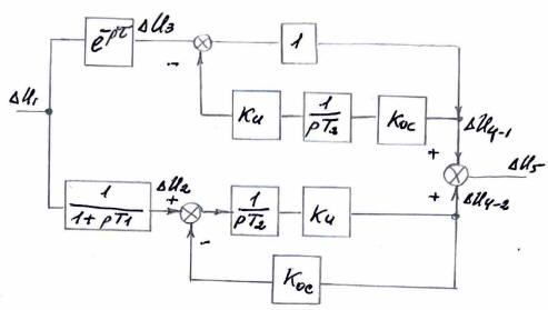
Note: Element designations
on the diagram (ΔU1, e-pτ, ΔU3, Ku,
pT3, Koc, ΔU4-1, ΔU5, ΔU2,
pT2, ΔU4-2) are kept in original Russian
layout.
|
|
|
|
|
| Let us
denote |
|
= K0
; |
|
= Tu
and |
|
= |
|
p · Tu · K0 |
|
1 + p · Tu · K0 |
|
|
|
|
|
|
= |
|
p · Tu · K0 · e-pτ |
|
1 + p · Tu · K0 |
|
+ |
|
K0 |
|
(1 + p · T1)(1 + p · Tu · K0) |
|
|
|
Substituting real values into
the expression:
|
|
|
= |
|
|
p · 0.15 · 4 · e-p · 0.0033 |
|
1 + p · 0.6 |
|
+ |
|
4 |
|
(1 +p·0.012)(1 + p·0.6) |
|
|
|
We find graphically (Fig. 8):
|
|
|
= |
|
|
4·(1+p·0.156)·e-p ·0.0033 |
|
(1 + p · 0.6) |
|
|
|
|
|
According to commissioning data: Kп1 = |
|
=
0.13 |
|
|
We find graphically (Fig. 8)
|