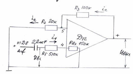
| 7.5.2.Amplifier Circuit |
18.2 |
|
 |
|
Note: Element designations on the
diagram (Д12, Uвх, Uвых, i1, i2,
iт) are kept in original Russian layout.
|
|
Uвх separates the AC
component
|
|
Uвых = i2·(R2+R3);
i1 << i2
Uвх = i2·R2
|
|
|
| 7.5.3. GД9(p)= |
|
;
TД9=0.047·10-6·200·103=0.0094s |
|
| 7.5.4. GД11(p)= |
|
;
T0Д11=1·10-6·200·103=0.2s |
|
D12 Amplifier Circuit - Part 2
| 7.5.5GД1(p) |
= |
|
KД13= |
|
|
= |
2 |
|
TД13=1·106·200·103=0.2s |
|
|
|
|
According to adjustment data
at Δf =1Hz, ΔUД8=0.5V, |
| Kf
= =0.5V/Hz
|
|
τ - pure delay, equal
to one voltage
period τ = 0.02s |
|
e-pτ is replaced
by the
link |
|
|
|
7.5.7. KП1, KП2
According to adjustment data |
| KП1= |
|
=
0.05 (Position of the
switch "KΔf"-1) |
|
|
|
|
|