| 7.3. Structural
diagram of the current unit (БТ) |
16 |
|
|
7.3.1. Actual circuit
|
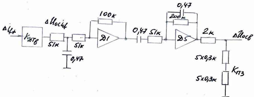 |
|
Note: Element designations on the
diagram (Д1, Д5, Кпз) are kept
in original Russian layout.
|
|
7.3.2. According to adjustment data
|
|
ΔUосIf = 10V at Δif
= 3850/0.817 by AC current
|
|
In relative units by DC current |
|
Δif* |
= |
|
|
|
|
| 7.3.3. Gд1(p)= |
|
; Tд1=0.47·10-6· |
|
·103=0.012s |
|
|
7.3.4.
|
Gд5(p)= |
|
p·T0д5 |
|
(1+p·Tд5-1)(1+p·Tд5-2) |
|
|
|
T0д5=0.47·10-6·200·103=0.094s
|
|
Tд5-1=0.47·10-6·51·103=0.024s
|
|
Tд5-2=0.47·10-6·200·103=0.094s
|
| 7.3.5. Kпз |
= |
|
=0.6
(Position of the switch "Iв"-10) |
|
|
7.3.6. Gбт(p)=Kдтв·Kпз·Gд5(p)·Gд1(p)=
|
| = |
|
Kотс.б·p·T0д5·Kпз |
|
(1+p·Tд1)(1+p·Tд5-1)(1+p·Tд5-2) |
|
|
V/pu |
|
|
Kпз·T0д5·Kдтв
= 0.6·0.94 · 4.62 =
0.26 |
|
|