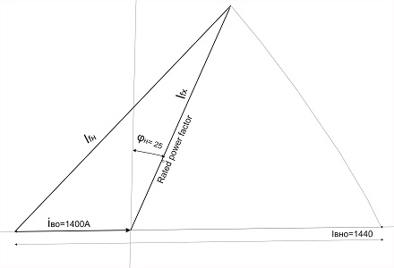
| Vector diagram for the excitation current
if0 |
12.2 |
|
 |
|
Fig. 5. Vector diagram for determining the
excitation current if0
at Ia=0, Iр=Iн,
cosφ=0 |
|
Definitions: |
iвo=1400A (no-load excitation current)
Jp=0, Jao=0 (zero active and reactive stator currents at no-load
baseline)
iвно - total reactive load field current
from Potier diagram (4440 A) |
|
|
The graphical construction is based on the fact that the
vector iвх is a geometric trajectory of the excitation current
variation during a complex increase in the generator load from
zero to the rated value, where the active current Ia
and the reactive current Ip increase in strict codependence,
maintaining the rated power factor of the machine.
At the final rated point (at the end of the vector):
The stator active current becomes equal to the rated active
current: Ia = Iн (the vector iвн intersects with the vector iвх).
The stator reactive current becomes equal to the rated reactive
current: Ip = Ipн. |
|
|